uFluidic Device
Introduction
Microfluidic (uFluidic) devices refer to systems with small liquid channels. Microfluidic devices can be used in fluid mixing, droplet generation, and fluid separation. There are many possible applications including medical diagnostics, DNA sequencing, tissue engineering, and environmental testing. By leveraging precise control over small volumes of liquids, microfluidic devices enable efficient and accurate processes, revolutionizing traditional methods and opening avenues for rapid, cost-effective, and portable solutions in a multitude of applications.
In microfluidics, achieving effective mixing poses a significant challenge due to the absence of turbulent mixing commonly observed in macro-scale fluid systems. Instead, microfluidic devices typically operate under laminar flow conditions within small chambers, where conventional mixing mechanisms are inefficient. To overcome this limitation, the next solution is chaotic advection, which leverages geometric intricacies or external perturbations to induce chaotic flow patterns within the laminar regime, thereby enhancing mixing efficiency. This necessitates innovative design approaches and precise control strategies to harness chaotic advection for homogeneous mixing.
Logic Behind Mixing Sections
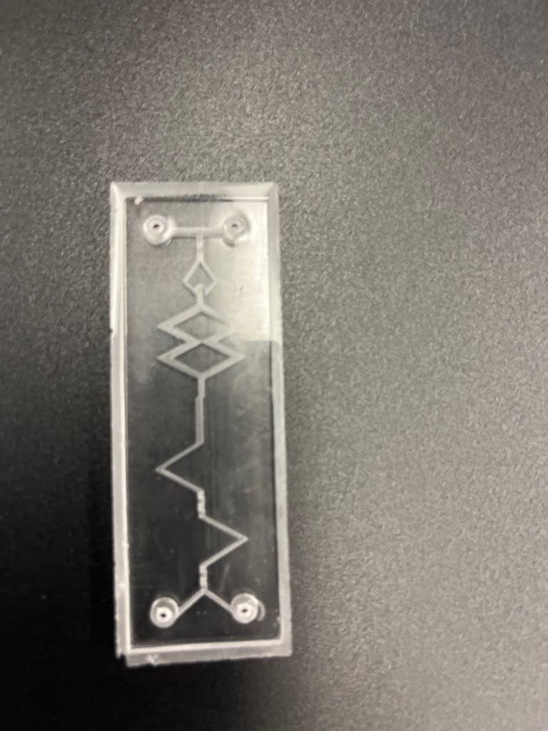
On the left side (top) of the device, the design principle for the mixing section includes a series of splitting flow paths, sharp corners, and inclined mixers to introduce chaotic advection. When the fluid enters the device, it comes into contact with another and splits into one pathway. Here, the contact and turn allow for mixing. After this division, the path contains a series of inclined mixers (4), which further disrupt the parallel flow. These inclined mixers are made with half triangles at a width, length, and height of 1 mm. After this short chaotic distance, the paths diverge, and then each path goes through a sharp turn, inducing chaotic advection. The pathways after the mixers are at a height and width of 0.5 mm. The individual channels then converge into a larger channel, increasing the cross-sectional area, which introduces another round of chaotic fluid behavior. The fluid then goes through a series of conversions, diversions, and a final turn to fully mix. These paths have a width and height of 1 mm.
Instructions
The fabrication process of the microfluidic device began with the creation of a mold using stereolithography. This mold, designed in CAD, was printed using a Formlabs Fuse 3 SLA printer and high-temperature resin. After printing, the mold underwent a washing process to remove excess resin, followed by a drying period and a brief curing step to prevent warping.
To address potential issues with resin leakage and compatibility with elastomers like PDMS, a thin layer of parylene was deposited onto the mold surface. This step enhanced biocompatibility and enabled the use of the resin mold for elastomeric device fabrication.
Subsequently, the mold was used to cast PDMS, a transparent and flexible polymer. UV light exposure induced curing of the PDMS solution poured into the parylene-coated mold, resulting in the formation of a new PDMS mold.
Finally, the PDMS mold was sealed using oxygen plasma treatment, which activated the PDMS surface and facilitated irreversible bonding with silicon-based materials like glass or silicon. This ensured the integrity of the microfluidic device.
In summary, the process involved designing and printing a mold via stereolithography, coating it with parylene to prevent leaching, casting PDMS into the mold, and sealing the resulting elastomeric device using oxygen plasma treatment.
Model
Video